Total Pageviews

Showing posts with label ELECTRONIC CIRCUITS. Show all posts

Sunday, May 2, 2021

電流帰還型オペアンプLMH6702を用いたトランスインピーダンスアンプの製作(1)

 ゴールデンウィークとなり、仕事のことを忘れて好きなことに時間を費やせるようになりました。昨年の11月頃に電流帰還型オペアンプTI社製LMH6702を使った中波DX用のSAL(Shared Apex Loop)アンテナ用のトランスインピーダンスアンプ(ループアンテナから出力される電流を電圧に変換するアンプ)を試作していたのですが、試作1号機は残念ながら異常発振を起こしてしまい、所望のトランスインピーダンスアンプとしての十分な動作が得られず、そのまま本職が忙しくなってしまい、さらにDXペディションも終わってしまったため、この試作機は、机の片隅に追いやられてしまいました。LMH6702は表面実装タイプのオペアンプであるため、そのサイズはとても小さく、老眼の私にとって基板上への取り付けはかなりの苦労を強いられたこともあり、その結果やる気がなくなり(苦笑)時間がだけが経っていったというのが正直なところです。

Fig.1 試作1号機(異常発振に悩まされた)


 年が明け、中近用の老眼メガネに加えて、パソコン作業やデスク作業用にと、近近用のメガネを新たに作ったところ、お陰様でデスク作業での疲れが半減しました。長時間本を読んでも疲れなくなりました。そしてようやく今回、再びチャレンジをする気力が湧いて来た次第です。

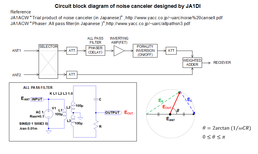
 LMH6702は、電流帰還型のオペアンプであるゆえ、その動作は電圧帰還型とはちょっと振る舞いが違います。電圧帰還型のオペアンプの場合は、+入力、-入力共に入力インピーダンスは大変大きく、理想的には電流は流れ込まないとして良いのですが、電流帰還型オペアンプの場合は、-入力は数十Ω程度しか入力インピーダンスがなく、電流が流れ込むことを逆に意識しなければならないこと等が違いとして挙げられます。電流帰還型オペアンプについて、Youtubeで大変わかりやすく解説してくださっている浜田智さんの動画があったのでご紹介させていただきます。電流帰還型オペンプによる、反転アンプの動作原理が理解できました。本当にありがたいことです。

 今日は、コロナ禍でもあるため、ずっと家に引きこもって、英文のLMH6702のデータシート等を読み漁っていました。データシートを読みますといろんなことがわかります、特にLMH6702の実装において注意しなければならないことを抜粋してみると、

  • 入出力端子付近にはGNDプレーン、電源プレーンは近づけないこと
  • 寄生容量が、帯域制限の原因となること
  • 電源ピンには高周波用デカップリング・コンデンサ0.1uFをLMH6702の電源ピンの直近に取り付けてGNDに落とすこと
  • フィードバック抵抗や入力に挿入する抵抗はLMH6702の入力ピンに最短距離で接続する、これら抵抗素子の反対側は、信号源あるいはグランドまでの接続距離は適宜長くすることは可能
  • フィードバック抵抗は273Ωの時がもっとも増幅帯域を広く取れる。この抵抗値より低いとピーキングが生じ、この抵抗値より高いと増幅帯域が狭くなる
こんなことが書かれています。基板に実装する際はこういったことに注意しなければなりません。試作1号もある程度は考慮していたとはいえ、例えば入出力端子付近にGNDプレーンを近づけないような配置にできたかというと、あまり自信がありません。また、入力ピンに最短で取り付けるフィードバック抵抗や電源ピン直下に取り付けるデカップリングコンデンサーもできるだけ小さいもの、表面実装タイプのチップ抵抗、チップコンデンサーがを使うほうがよりいいのでしょう。
 しかし、言うは易しだが行い難しとはこのことで、ユニバーサル基板上でこれをやろうとすると中々大変な作業になります。またGNDプレーンや信号線の引き回しをどのようにアレンジするのが適切なのか?も色々迷いが生じます。どこかにいい手本は無いものか?

 LMH6702のデータシートを読んでみると、評価用ボードの紹介がありました。手元にあるLMH6702はSOCタイプの8ピンICで、これを評価するボードがTI社から発売されていることを知りました。それがこれ、LMH730227です。大きさは約3.9cm四方です。

Fig.2 LMH6702(8Pin SOICタイプ)の評価基板LMH730227(表)
(IC周辺のGNDパターンは取り除かれている)


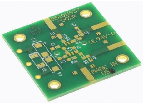
Fig.3 LMH6702(8Pin SOICタイプ)の評価基板LMH730227(裏)


Fig.4 LMH6702(8Pin SOCIタイプ)の評価基板LMH730227(データシート)

 パーツのネット販売で検索してみるとDigiKeyにて1枚1300円程度で手に入ることがわかったので、早速4枚注文しました。1週間程度で配達されるようです。8Pin SOICタイプのLMH6702のピン配置は次のようになっています。

Fig.5 8Pin SOICタイプのLMH6702のピン配置

6番ピンが出力で、その隣の7番ピンが+電源になっているのには閉口しました。しかし評価基板では基板の両面を使って、お互いの信号、電源線がぶつからないようになっていますし、またICチップ周辺のGNDプレーンは削られているようです。なるほどこのパターンを真似ればいいのか! 

GW中は時間が取れるので、ユニバーサル基板と銅箔テープを使って、この評価基板に似せた基板で回路を実装してみようと思います。評価基板が届きましたら、評価基板で作ったものとの性能評価の比較をしてみたいと思います。

Monday, May 27, 2019

I switched on my old RF instruments for the first time in 3 years.

 3年ぶりに、RF測定器達に電源を投入してみた


  RF instruments are needed to make a precise RF combiner and preamplifier for SAL antenna.  I picked up my old RF instruments from cardboard boxes in my room and switched on them for the first time in 3 years.  They are all second-hand instruments that I bought without the permission of my wife (hi-hi).  They worked again very well.  I told my old RF mates,

Kept you waiting huh?

 SALアンテナの製作のためには、精度の良いコンバイナーや、プリアンプを自作する必要があります。となると測定器は必須。単身赴任時代にカミさんに内緒で買いためていた中古の測定器達を引っ張りだし、電源を投入してみました。無事に動いている様子。

「待たせたな相棒!」


Fig.1 Tektronix 2455B 

Fig.2 KIKUSUI KSG 4300
I let them do heat running and stick around in my room tonight. 
とりあえず今夜はヒートランをして、彼らにはくつろいでもらおう。

  My current probes are cheap and doubtful Chinese probes so I'm considering of buying good ones. And I might have to ask some dealers for adjustment and calibration for serious measurements. 

オシロスコープ用のプローブは中国製の怪しいものしかないので、少しいい奴を買おうと思う。本格的にやるなら、一度調整・校正にも出さないといけないかもしれないですね。

Wednesday, April 10, 2019

How to Install LMH6702 macro model to LTspice XVII


-----How to set up a new opamp model to Ltspice XVII-----
1. Download the opamp macro model from its manufacturer.
2. Put .lib or .mod file of the opamp to C:\Users\Username\Documents\LTspiceXVII\lib\sub
3. Make .asy file of the opamp by using opamp2.asy and put it to
C:\Users\Username\Documents\LTspiceXVII\lib\sym

You can get the SPICE MODEL of LMH6702 from here. 

This is a comparison of open loop gain characteristic of LMH6702 between Ltspice XVII and Datasheet. The absolute values don't match but the relative value of the gain and phase and the position of poles are almost the same. 


Friday, February 8, 2019

VNAを発注

 昨年から、購入を検討していたminiVNA Pro2を一式発注しました。日本国内のショップで買うより、ドイツのWiMo Antennen und Elektronik GmbHから購入した方が格段に安いです。(支払いはユーロで現地決済)これ、Bluetooth内蔵なので、ワイヤレスで、データの取得等が可能とのこと。ただ、このVNAは、Bluetooth対応フリーソフト(BlueVNA)に未対応との情報がありましたので、開発者にメールで問い合わせ中です。(本家サイトには、ユーザーレポートとして「動いている。」という報告もありましたが...。)


 今年は、これでインピーダンスマッチング用のトランス等、実験・製作してみようと思っています。あと中波DX用アンテナも! 実験結果等はこのブログで紹介していきます。下の動画は、Kevin Loughin(KB9RLW)さんによる、紹介ビデオです。


Tuesday, February 5, 2019

Design of impedance matching transformer (1)

 This year is expected to be the best year of MW DXing for the first time of 11 years. So I am planning to build D-Kaz antenna by myself.  I need to make an impedance matching transformer that converts the antenna impedance around 800 ohms to 50 ohms of the input impedance of SDR effectively.
  To design the transformer, I needed to review a reactance circuit with mutual inductance.  I read some textbook that I used to refer to in my college days a long time ago.

  Figure1 shows an impedance matching circuit using a transformer. The resistance of each coil is ignored.

Figure1 an impedance matching circuit using a transformer 
From this figure, the following formulas can be obtained.

(These formulas are revised on Feb.6 2019)

  From these formulas, I can understand that a primary impedance Z1 is matched by secondary impedance R2 by the ratio of primary and secondary coil turns. However, the following condition is required to let the circuit work properly.


 I am wondering what multiplier α should be applied to obtain reactance of L1.
I am trying to find the clue to decide α in several references and textbooks.

According to the paper of "Impedance Matching Transformers for Receiving Antennas at Medium and Lower Shortwave Frequencies" written by Bill Bowers, John Bryand and Nic Hall-Patch, They say that the reactance of primary winding coil may be found by multiplying the impedance of the antenna to be matched by a factor of 4. They are unaware of any empirical data that has been published to support the value of this particular multiplier being equal to 4. During Bill Bower's study of impedance transformer design for LF use, his data support a K value much more nearly 6.

 I am still struggling for understanding how to design the impedance matching circuit using a transformer.  I would very appreciate if you could give me any suggestion.


Monday, October 1, 2018

Perseus SDR用DC5V電源の製作

 来週末、三陸方面に中波DXペディションに出かけるため、ペルセウス用のDC5V電源を製作しました。実は、過去に1台作ったのですが、どこかのペディションで紛失してしまい、再度作りました。参考にした回路図は、KAGEYAMA BCL AUTOPAGEで紹介されていたものを参考にさせていただきました。DC6V出力のトランスタイプのACアダプターを接続することで、三端子レギュレーターを使って最大1AのDC5Vを出力することができます。少し電源スイッチ照明にこだわって、スイッチそのものが発光するようにしてみました。しかし53歳の目には、細かい部分のはんだ付けはつらいものがありますね。またコンデンサー類の数値も読むのはかなり辛いですね。ハズキルーペが欲しくなりました。今回は手元にあった、この巨大なルーペを使いました。まあこれが今回大活躍したわけですが、近いうちにハズキルーペ買うつもりです。 

ルーペ下部に単四電池3本入れることで、LED照明も点灯します


電源をONすると発光ダイオードによりやわらかい黄色の色でスイッチが発光します。部屋を暗くしても目に優しい感じです。

放熱のため天井に三端子レギュレーターをつけています(ねじ止め)

ハズキルーペのCMとても面白いですね。渡辺謙さんの主張、大いに頷けます。


Wednesday, September 5, 2018

Noise cancelling by dual Afedri receiver and Linrad

とても気になる動画を見つけてしまいました。(気が付くのが遅いことを後悔しています。)Linradはもっとサイトを読み込まなければ。 今夜は取り急ぎご紹介まで。なにやら二つの同期のとれたSDRを使って、適応処理によるノイズ除去が実現できている様子。適応アルゴリズムは一体どんなものを使っているのでしょう。一体何をもって「適応」なのか?

     I found a very interesting video tonight. ( I really regret that it was late to notice it.)  I need to study about Linrad more. Tonight, Just quick notification.
This video seems to show adaptive noise cancelling by two SDRs and Linrad.


 次の動画は、同様なノイズキャンセルを2台の同期の取れたSDRを使って実施している様子です。説明を聞いている限りでは、ノイズセンシングアンテナがきちんとノイズを捕まえていないと、うまくノイズキャンセルできないようで、従来のMFJのノイズキャンセラーと原理は同じようです。前者の適応的というのは、ノイズの位相が変動してもそれに適応的に追従して、つまり、MFJの場合は、ユーザーがいちいちボリュームを回して位相追従していたところをオートマチックに位相追従を実現しているということなのでしょうか。


Monday, August 27, 2018

My impression of Ham Fair 2018

   I went to Tokyo Ham Fair 2018 at Tokyo Big Site on Aug.26.  It was such a hot and sticky weather, and I felt like I was in a steam oven or sauna.

今日は茹だるような暑い日でしたが、ハムフェア2018を見に、東京ビッグサイトへ行ってきました。


   Today was the second day of the fair so that the number of visitors didn't seem to be so many. Japanese transceiver manufacturer like KENWOOD, YAESU and AOR were exhibiting their transceivers and their accessories at each booth. The exhibits were not so new things to me. The colourful display of SDR such as waterfall and frequency spectrum has already been a standard function of amateur radio transceivers. The basic concepts of reception dynamic range enhancement and noise cutting have not changed at all.  The large and heavy u-tuning circuit unit made by YAESU was eye-catching to me, but the technique is very old-fashioned one that was used in a rocket-shaped crystal radio in my elementary school days. But there must be some know-hows to achieve high resonant Q value of the circuit by choosing optimum devices and case.


今日は、2日目だったということもあり、来場者の数はそれほど多くありませんでした。ケンウッドや、ヤエス、AORといった大手の展示ブースを見て回りましたが、内容的には特に新しいものは感じられませんでした。SDRではおなじみのカラフルなウォーターフォールや周波数スペクトル表示機能は、デスクトップ型のアマチュア無線機にはもはや常識となってしまっていますね。受信ダイナミックレンジ改善や、ノイズ除去技術の基本的なコンセプトはずっと変わっていないようです。大きくて重たいヤエスのμ同調回路ユニットは目を引きましたが、これも特に技術的に新しいということでもないですよね。自分が小学生の頃に売られていたロケット形の鉱石ラジオの同調回路にも使われていました。ただ、きっとケーシングや部品の選定等で、高Q値の実現等のノウハウは隠れているとは思います。

YAESUのu同調回路ユニット ダイナミックレンジのIPが4dB程改善されるらしい。
μ同調型のロケットの形をした鉱石ラジオ
ロケットの先のピンを出したり引っ込めたりするとコイルの中のフェライトコアが上下する仕組み

    Many tiny antenna analyzers were displayed in the fair. Most of them were the 1-port type. The price range was between about 28,000 yen to 50,000 yen.  
This is an introduction video of impedance and antenna analyzer SARK-110 by Seed in China. SARK-110 has a spectrum analyzer and a signal generator, and you can make the small display to big one by using your PC display too. Frequency range is from 100kHz to 230MHz. 

  ハムフェアでは、とても小さなアンテナアナライザーが沢山展示されていました。ほとんどのものは1ポートタイプです。価格は28000円から50000円の間です。この紹介動画は、中国のSeedが生産しているSARK-110というインピーダンス/アンテナアナライザーです。簡易スペクトラムアナライザー機能と信号発生器にもなります。小さな画面も、USBでPCに接続すれば、PCの大画面で測定することも可能。周波数は100kHz から230MHzをカバー。


   This is an introduction video of a new Vector antenna analyzer  FA-VA5 made by Funk Amateur in Germany. The frequency range is from 10kHz to 600MHz, much wider than SARK-110. The FA-VA5 also works with another VNWA software running on a PC via USB connection. You can see the bigger measuring screen. You can purchase a kit of this analyzer too.
こちらは、ドイツ Funk Amateur より発売された新製品 FA-VA5 ベクトル・アンテナアナライザーの紹介動画です。周波数は10kHzから600MHzと先のSARK-110より広帯域です。こちらもUSB経由で他のVNWAソフトと連携でき、大きなPC画面で測定できるようです。キットでも販売されています。

   These are very well-known, popular antenna analyzers from MFJ. The prices are also reasonable. 

  そして、こちらはおなじみのMFJのアンテナアナライザー各種です。最近はグラフ表示できるものが増えていますね。お値段も手頃です。


  Well, What kind of analyzer do I want?  I would say I want to have a VNA for 2 port measurement. Measurement of input-output characteristics of filters needs the function. To design and make good filters and resonant circuits, a VNA for 2 port measurement is very helpful.  Many OMs who introduce their good hand-made circuits on their blogs seem to have instruments like these VNAs. I am interested in miniVNA Pro2.0 from mini Radio Solutions now.

   では、私がどんなアナライザーが欲しいかと言えば、2ポート測定ができるものでしょうか。フィルター特性等の入出力特性を測定しようとなると2ポート測定ができるものが欲しくなります。結局のところ、きちんとした特性のあるフィルターだとか、共振回路だとかアンプ等を作ろうとすると、最低、信号発生器(SG)とオシロスコープがあれば測定は出来なくはないですが、こういったVNAがあるととても便利ですよね。素晴らしい自作品を多数発表されているOMさん達の様子を見ているとたいてい、こういったツールはお持ちでいらっしゃるようです。今、自分が気になっているのは、mRS社のminiVNA Pro2.0 です。


Friday, August 17, 2018

MFJ 1026 Signal Enhancer/Noise Canceler

  The MFJ 1026 has been famous noise canceler.   This video shows that its great effect for annoying noise on HF band. From this video, noise on the bandwidth of about 200kHz seems to be eliminated very well. I would like to check the circuit diagram of MFJ1026 in near future.

  MFJ1026は、昔から有名なノイズキャンセラーですよね。この動画は、HFバンドでのその素晴らしいノイズ除去の様子を紹介しています。この動画を見る限り、帯域200kHz程度のノイズは非常にうまく除去できているようです。MFJ1026の回路がどんな構成になっているのか近いうちに調べてみたいと思っています。


Thursday, August 16, 2018

A preliminary study on noise canceler for MW DX

    For MW DXing, the problem of noise is annoying matter. It will be the worst experience if noise can be heard on all the MW band in the case of going to remote DX expedition place even though spending a lot of time to prepare for the expedition with much efforts.
    I often talk about problems of noise with my friends of MW DXer. Most of them worry about the issue.
    As far as I know, Figure 1 shows the relationships between frequency and medians of measure noise in 2005 and 2007 and the pink line represents the ITU-R P.372-8 noise figure estimated in the business category (Ref.1).  The frequency for the measured noise is on HF band, but unfortunately, we could say the noise level on MW band become much larger than the noise figure shown in the ITU-R P.372-8 that data was measured in the 1970s (Very old data !! ).  Even in the rural area, I believe the noise figure has the same tendency.  It is so pity, but it can't be helped at all.

Fig.1
Ref.1 Miki Iwama, "Estimation of Background Noise in HF-band",2008 APEMC

    To overcome this annoying problem of noise, I started a preliminary study of noise canceler. There are a lot of reviews on noise cancelers among ham DXers and MW and SW DXers. In Japan, the famous noise canceler circuit would be one that introduced by JA1DI, Mr.Yamaguchi.  His original circuit is shown here by JO7NLI, and many Japanese DXers made this circuit to eliminate noise. The author of "Saitama Radioholic Intl" reported the fight with a neighborhood air-conditioner noise with his modified circuit in his blog, and Mr Kageyama also introduced his modified circuit based on the JA1DI's circuit too, and  All of them have confirmed that the circuit works very well for certain kinds of noise.
    Figure 2 shows the circuit block diagram designed by JA1DI's noise canceler. Thanks to the detail description by JA1ACW, I could understand how this circuit works to eliminate noise.

Fig.2 Circuit block diagram of noise canceler designed by JA1DI

   It is interesting to know the all-pass filter works as a phaser. Changing phase means that the inputted signal is also delayed. But please note that the time delay of the signal depends on the frequency of the signal. And the group delay characteristic of the all-pass filter is NOT constant. It means that the delay time is not constant for all the frequencies. It is very important to understand that this noise canceler can eliminate the noise on a certain minimum frequency band at the same time and I think this canceler is not appropriate for a reception recording all MW band by SDR (Software Defined Radio).   One of my friend of MW DXers whom I respect suggested to me that the noise comes through multipass including skywave reflected by ionospheres and the phase of noise changes with time and the phase and gain adjustment on the weighted adder would be needed accordingly. I will show the group delay characteristic of this circuit on this blog later.


Monday, August 13, 2018

Learning RF transformer circuits by SPICE

    There is no doubt that RF transformer circuits are very important for impedance matching of antennas and RF signal processing on analogue circuits. However, understanding these transformer circuits is not easy because we need to consider reactance behaviours on radio frequency very well and we also have to know how to make it by winding coils on ferrite cores. So we need to understand concrete winding methods too. The characteristics of ferrite cores are also complicated. There are some textbooks to understand RF coils including ferrite characteristics but only reading textbooks is not perfect for practical application. We need another better methods to confirm the response of circuits with RF transformer. I think the reason why RF transformer circuits are not easy for many radio hobbyists is that we don't have enough electric instruments like oscilloscope etc. and it is true that we also don't have enough time to do experiments using "real" RF coils. Making real RF coils is time-consuming and bothersome for just only experiments.
     I decided to use SPICE software to simulate RF transformer circuits. I would like to learn typical RF transformer circuits by using SPICE. SPICE is free! After downloading the software of SPICE, I could simulate an RF transformer circuit within 1 hour. SPICE is very easy to use. Happy simulation!

  RFトランス回路は、空中線のインピーダンスマッチングやアナログ回路における高周波信号処理には非常に重要であることは疑いの無い事ですが、このRFトランス回路をちゃんと理解するのは簡単ではないですよね。(少なくとも私にとっては簡単ではありません。)なぜなら、高周波におけるコイルの振る舞い等を熟知していなければなりませんし、実際にフェライトコア等にどのようにコイルを巻くのかについても知っていなければなりません。フェライトコアの特性も結構複雑です。いくつか教科書はありますが、単に教科書を読むだけでは、実際の回路製作等への応用には不十分です。自分が設計したRFトランス回路の応答等を確認できるより良い術が必要です。無線を趣味にしている私を含む多くの方々にとって、なぜこのRFトランス回路が鬼門なのかというと、やはりそれは、回路を測定するためのオシロスコープ等の測定器を充分に所有していないということがあるかと思います。さらにまた、本物のコイルを作って、それを用いて実験をする充分な時間が無いのも正直なところだと思います。実際にコイルを巻いて、それを使って測定系を組んで、実験をするのはとても時間がかかりますし、単に実験するだけのためにコイルを作るのは結構面倒なことですよね。そこで、私は、SPICEを使ってRFトランス回路の勉強をすることにしました。SPICEは無料ですからね。さっそくSPICEをダウンロードした後、1時間程度で、練習がてら適当に組んだRFトランス回路のシミュレーションがさっそくできるようになりました。SPICEはとても使いやすいですね。 ただ、ここにも書いてあるとおり、シミュレーターで上手くいったからといって、シミュレーター通りの動きに実際の回路がなるかというと、浮遊容量だとか、インダクタンスがある周波数以上ではキャパシタンスになってしまうなど、そうは問屋が卸さないわけで..。シミュレーターは新しい回路の方式を考案した際に、手早く短時間でその効果を検証したり問題点を把握したりできる「アイデアを試すツール」、回路の動作やパターンを利用した高周波部品の振る舞い、インピーダンス整合などを学ぶための「学習ツール」として使うのが適切なようです。またシミュレーション結果を鵜呑みにせず、理論的にもきちんと腹に落とすことが大切ですよね。Happy simulation!